| 📝Contents |
Inside the Design Canvas
The CELUS Design Canvas is the workspace within the CELUS Design Studio where you can plan, design and execute your electronics projects seamlessly. It provides all the necessary details to expedite the development of a functional electronic product, ranging from high-level block diagrams to interconnecting multiple functional circuits on a simple whiteboard. Additionally, you can create a Bill of Materials (BoM) for your project and generate the Electronic Design Automation (EDA) files required for building your PCBs, all within a single application. Below is a step-by-step guide on how to build a project from scratch.
When you select the option to start a project from scratch you will be greeted by an empty workspace in the CELUS Design Canvas as shown in the figure below. When starting a project from scratch, you are presented with an empty Design Canvas, with tools available on both sides of the interface to assist in structuring your design.
 CELUS Design Canvas: 1) Undo/Redo and Resolve button 2) Design Library Panel 3) Error/Warnings Panel 4) Navigation Tabs 5) Canvas Settings 6) Design Assistant 7) View Settings
1) Undo/Redo and Resolve button
The Undo/Redo button helps you revert the actions performed in CELUS Design Canvas. The Resolve button is inactive by default. However, if you have the project design ready to resolve, the Resolve button will be active . Once the Resolve button is pressed, you cannot undo the action or revert the changes made on CELUS Design Canvas.
2) Design Library Panel:
The Design Library panel, displays the list of Functional blocks and their categories available for designing an electronics project. To gain more insight into the concepts of Functional blocks, please visit the page. You can also search the name of functionality in the top searching bar, and the search term will be highlighted in grey across blocks within Library Panel. User can close the Library Panel if they tap on the handle, and can re-open it if they tap again on a handle.
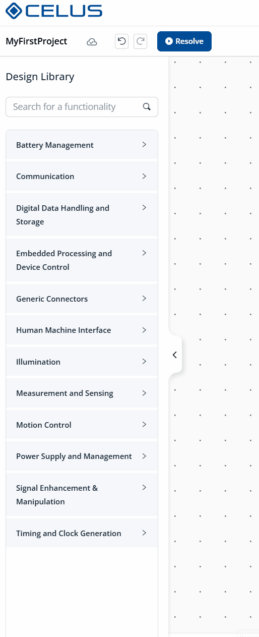 Design Library Panel
3) Error/Warnings Panel
When a project fails to resolve in CELUS Design Studio, errors and warnings will appear in the Notifications panel at the bottom of the Design Canvas.
- The affected functional blocks will be marked with a warning symbol.
- The Errors/Warnings panel shows the total number of issues.
- Clicking the error or warning icon will expand the panel to display detailed information about each issue.
This helps you quickly identify problems and understand how to fix them.
The Errors and Warnings Panel provides actionable feedback when issues occur during project resolution.
- Each entry includes a description of the problem.
- Clicking on a specific error or warning highlights the related element directly on the Design Canvas.
- This makes it easier to troubleshoot and continue your design workflow efficiently.
Enhanced error messages and visual highlighting of related Blocks and interfaces
4) Navigation tabs
Design Studio comprises three stages: Design Canvas, BOM View and Output Files. Once you have completed filling in the details in Project Settings, the CELUS Design Canvas tab will be activated, allowing you to commence the project creation process. Upon resolving the project in the CELUS Design Canvas, the BOM view and Output Files stages will be activated for review.
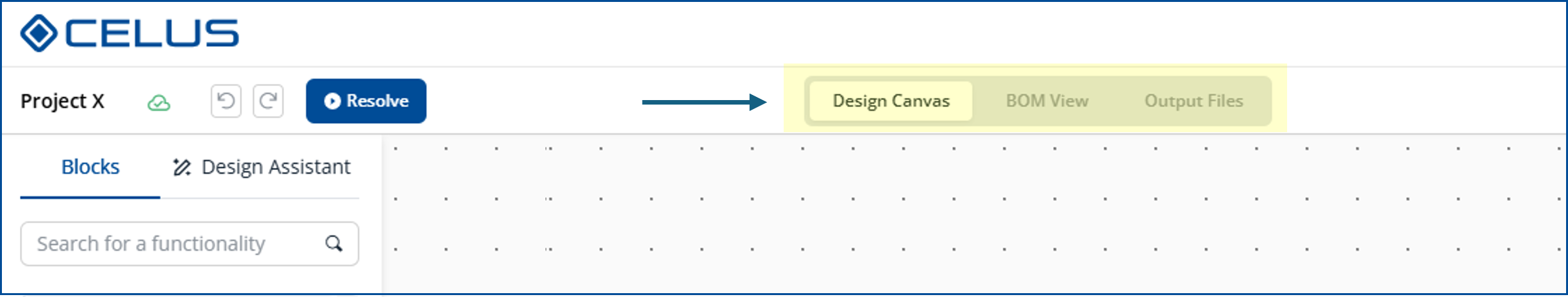 Navigation tab: Design Canvas,BOM View,Output Files
5) Canvas Settings
Access to Project Settings, and Project Share options.
- Project Settings: Define your project details, including preferred manufacturers, components, technical constraints, and other requirements.
- Share Project: Share the project link with peers or make your project publicly accessible.
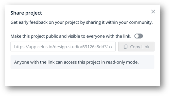
Share Project: Enable Public Sharing of your Project
6) Design Assistant
AI-Powered Design Commands (Text to Canvas and Image to Canvas) enables users to generate and refine designs using simple text prompts. Users describe what they need, and the AI materializes their intent directly on the canvas. Users can enter natural language commands to interact with the design tool. AI can place and modify design elements based on user instructions. By refining prompts and accepting AI-generated suggestions, users can rapidly iterate and build designs with ease.
Create projects with Design Assistant and iteration of the design with consecutive commands
By lowering the barrier from concept to prototype, the Design Assistant supports both novice and experienced engineers in streamlining architectural design.
🔍Explore more: Accelerating Electronics Design in Canvas using Design Assistant
7) View Settings
The Pan over screen button which helps you navigate the CELUS Design Canvas workspace. Next to that are the Zoom In and Out buttons, and the Fit to Screen button in the middle.
Configure the design
Select the CUBO™
Once your project has been resolved, all Functional Blocks will be populated with at least one matching CUBO™. By default, the CELUS Design Platform automatically selects a recommended CUBO™, marked with a purple CELUS recommended tag. You can explore additional options by clicking See more CUBO options, which will open the CUBO Results screen. Here, you can review alternative CUBOs, examine their schematics and metadata, and select a preferred implementation. If desired, you can lock a specific CUBO™ directly from the results view. Alternatively, you may proceed with the CELUS-recommended option. Once you confirm your selection by clicking Lock in the Settings panel, the button status will update to Locked, and the label will change to Selected by you, indicating that a user-defined selection has been made. For a detailed walkthrough of the CUBO™ Results interface and further selection mechanisms, refer to the chapter titled Select CUBO™.
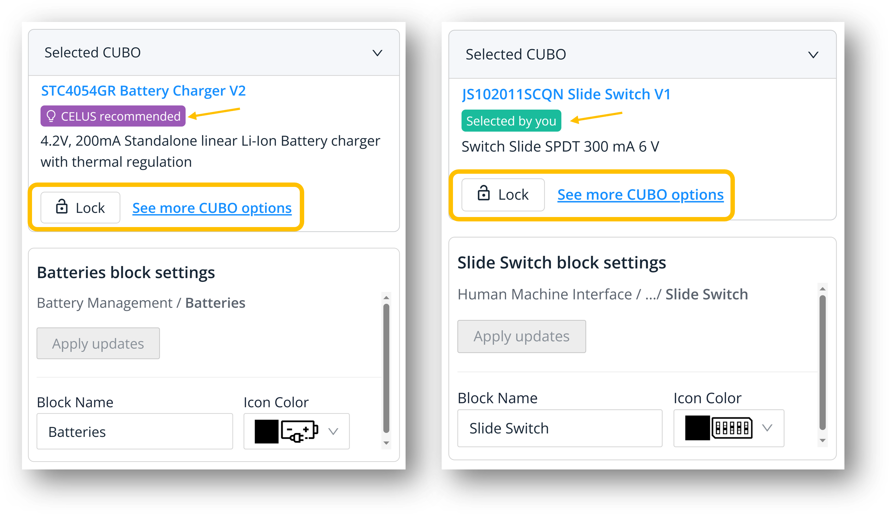 1) CUBO™ recommended by CELUS 2) CUBO™ selected by you
Delete / Duplicate a Functional Block
To Delete or Duplicate a Functional block, first, you need to right-click on the Functional block. Then select Delete to remove the Functional Block or select Duplicate to create another copy of the Functional Block.
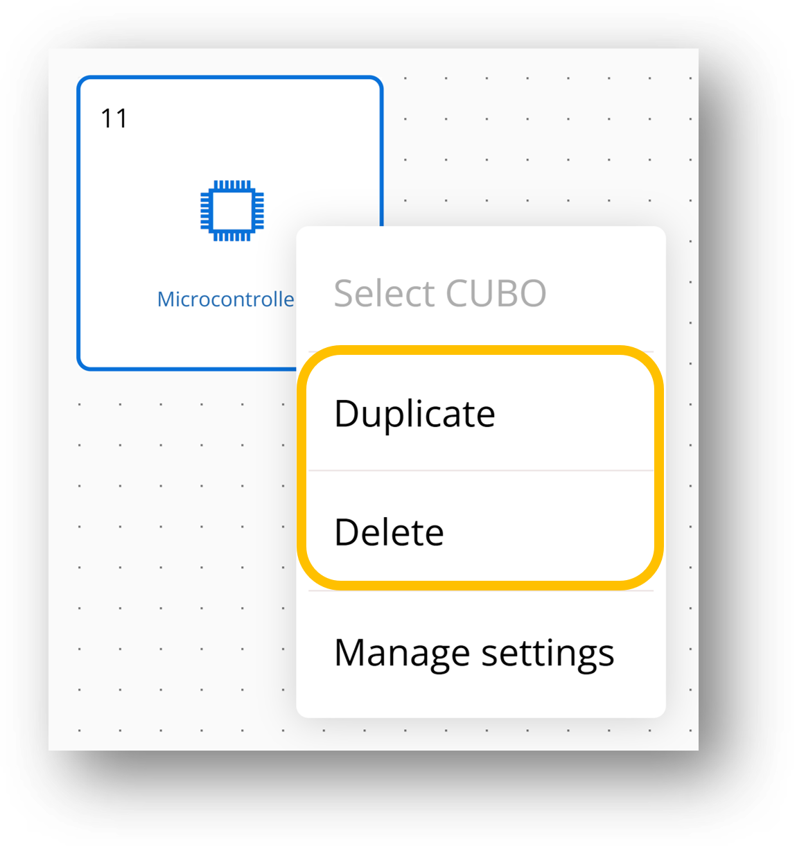
Delete / Duplicate a Functional Blocks
Move or Resize Functional Block
To move a block in Canvas, first, you need to select the block by left-clicking with the mouse. Once the block is selected, a drag icon ![]() appears, indicating that the block is ready to be moved.
appears, indicating that the block is ready to be moved.
You can resize the block by selecting the resize icon shown in the figure below, located at the corner of the block, and dragging it across the grid.
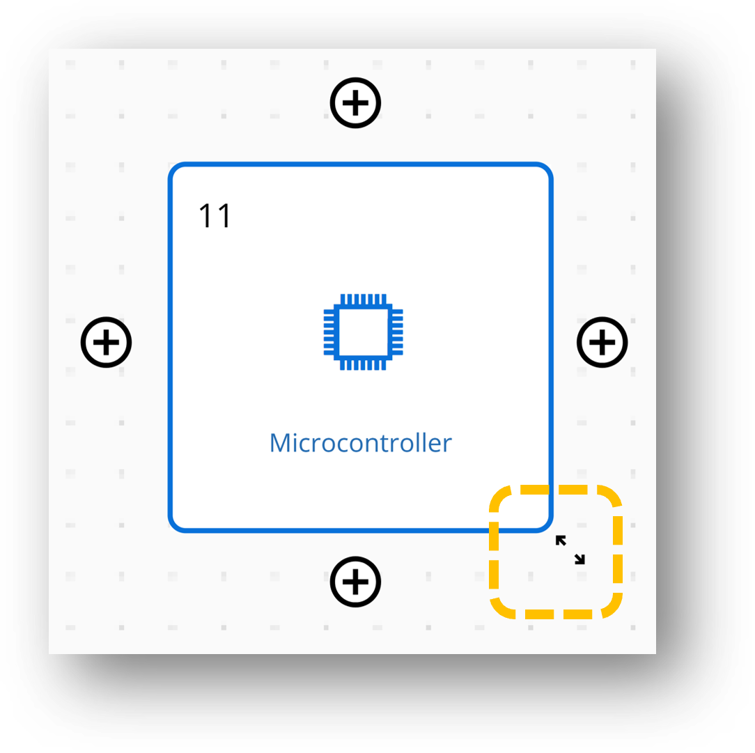 Resize the Block
Adding Ports to Functional Block
Establishing connections on CELUS Design Canvas between Functional Blocks is facilitated by Ports and Links.To start, add Ports to a Functional Block by clicking on it. This will display the Add Ports button with a plus icon on all four sides. You can add Ports to any side of the block, depending on the desired connection direction. Clicking the Add Ports button creates a Port on the corresponding side, and additional Ports can be added by clicking the icon again.
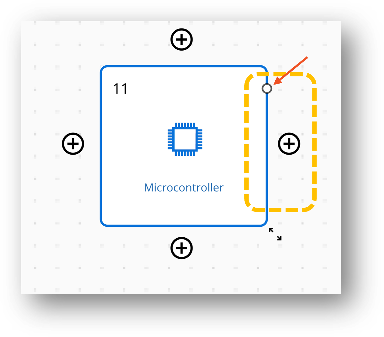
Adding Port to the Block
Connect Functional Blocks via Links
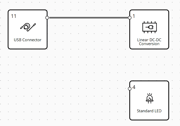
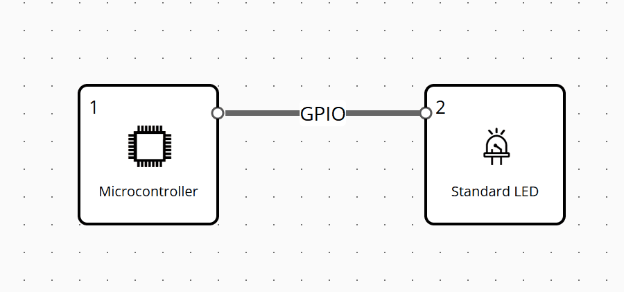
To connect two Functional Blocks in the CELUS Design Canvas, use Links which act as virtual wires between CUBOs. Start by adding ports to both the transmitter and receiver blocks. Then, hover over a port until a crosshair icon appears. Left-click on the port and drag it toward the destination port.
A Link is created when the cursor at the connection end turns Yellow. Left-click on the receiver port to finalize the connection. The Link will turn Blue, indicating a successful connection.
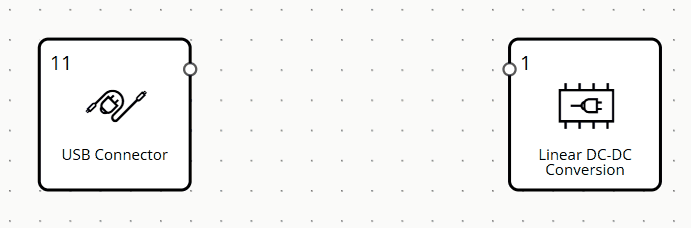
Connecting Functional Blocks using links
Branch and Move Links
To establish a T-connection or a Star Connection from a Link, first, you need to click on an existing Link from which you want to branch out. Then, the Branch Link icon ![]() appears on the Link. Left-click and drag from the icon to branch out the Link and go to the Port where you want to establish the connection.
appears on the Link. Left-click and drag from the icon to branch out the Link and go to the Port where you want to establish the connection.
 Establishing T-Connection among Functional Blocks
To refine your project design, you can easily rearrange links after establishing connections using the Move Link feature. First, left-click on the link segment you want to move. Once the plus icon appears, click it, and a dark round icon will indicate that the link is ready to be moved. Then, left-click on the round icon and drag it in the desired direction. As shown in the figure below, ports are highlighted to facilitate establishing connections.
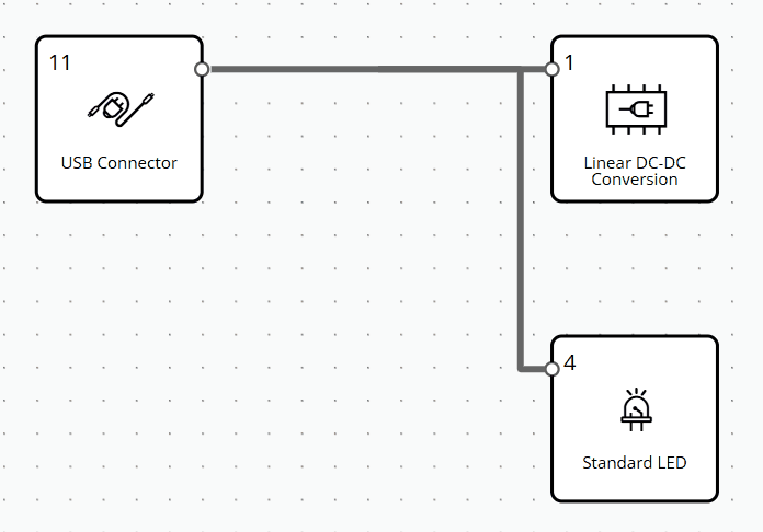 Moving Links in Design Canvas
Link Settings and Assigning Ports to Links
In the CELUS Design Studio, interface assignment between Functional Blocks is typically handled automatically. Once you resolve a project, the platform’s AI engine intelligently maps compatible interfaces to Links, virtual wire connections between blocks.
However, if you need to explicitly define port-to-port connections between blocks:
- Right-click on a Link in the canvas and select Manage settings or simply left-click on the Link.
- This opens the Link and Port Settings panel on the right-hand side.
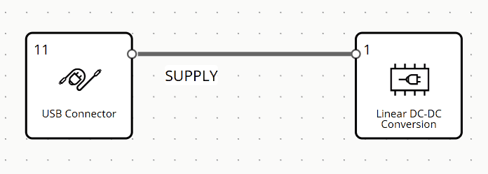
- Use the interface search bar to choose a shared interface supported by both connected functionalities.
- Select a Port Type, then choose the desired port by typing or scrolling through the list.
- Click Apply updates.
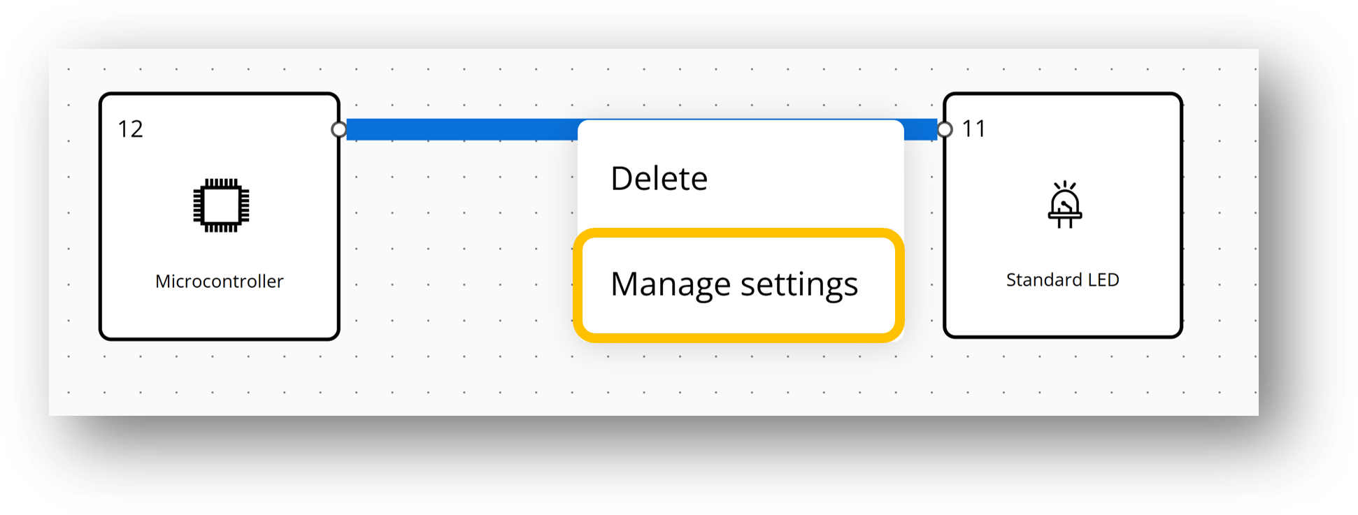 Manage settings: configure the Link
Selecting Interface from Link and Port Settings Panel
Note: If the interface connects to multiple blocks, the related ports will not yet appear under Available Ports. This capability is planned for a future release.
Place Port Labels
Once you assign ports to a Link and enable the Show Label toggle, the port name becomes visible directly on the Link.
To reposition the label:
- Left-click on the label until the drag icon appears.
- Drag the label to your desired position.
Note: Port label movement is constrained by the orientation of the Link segment:
- If the segment is vertical, the label moves vertically.
- If the segment is horizontal, the label moves horizontally.
 Repositioning Port Label
Resolve Project
Projects you create with Design Assistant, along with any changes you make (such as connecting functional blocks, assigning ports, and adding labels), are automatically saved by the CELUS Design Studio.
To complete your project resolution:
- Click the Resolve button on Canvas's top ribbon.
- Wait a few seconds while the system processes your design.
- A purple icon will appear in the top-right corner of each functional block, showing that the resolution was successful.
- Once resolved, the CUBO Results page on the Design Canvas will display the generated CUBO™ solutions for each block.
 Successful resolution of Project
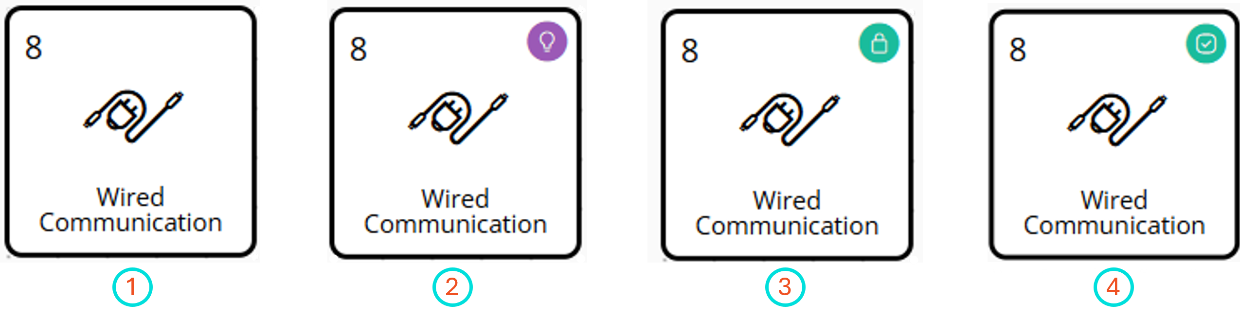 Block status: 1) Before Resolve 2) CUBOs found after Resolve 3) Select and Locked the CUBO 4) Unlocked the CUBO
Start using CELUS Design Platform and stay tuned for new updates